
1-805-484-2992
Quotes - Engineering - Sales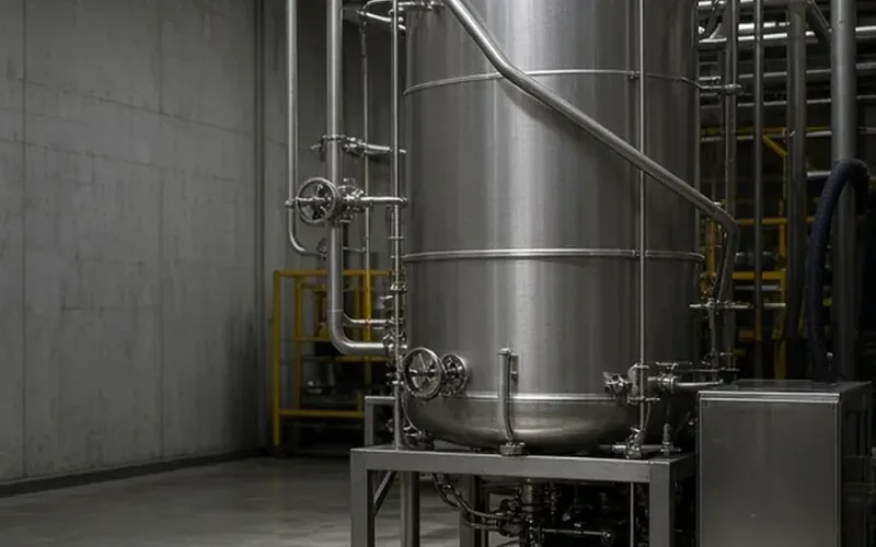
The circuit decides the heater, then the duty sizes it
A CIP heater sits in the cleaning loop, not the product line. What flows through it is 1–2% sodium hydroxide, dilute nitric or phosphoric acid, or rinse water on its way to a tank, a spray device or a pipeline circuit. The product the plant is washing off never enters the exchanger, so the first question is not what the plant makes but which wash step the heater serves. Caustic, acid, hot-water rinse and heat recovery each put a different fluid, temperature and fouling pattern on the solution side, and that is where selection starts.
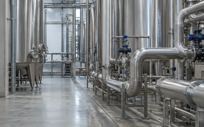
Once the circuit is named, the duty follows from four numbers: flow in gpm, inlet temperature, target temperature and the steam pressure available at the heater inlet. A tank recirculation heater on a 2,000-gallon caustic tank has a 20-minute heat-up to meet; an inline heater on a 70 gpm 3-inch supply line has to deliver 160°F on every pass with the steam valve following the flow. The two might carry the same Btu/h rating and still be sized, valved and piped quite differently, which is why the circuit pages ask for tank or once-through before anything else.
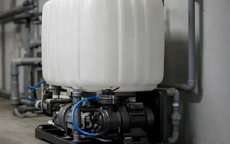
Construction comes last and is usually settled by two things: what fouls and whether it has to come out. On a caustic heater the solution side fouls with milkstone, protein and carbonate scale while the steam side stays clean, so the bundle that touches caustic is the one that pulls. Where two liquids exchange heat at modest pressure, a gasketed plate pack with the elastomer matched to the chemical does the same work in a smaller frame. The table below is the short version of that logic; each row links to the construction it names.
Which construction each duty usually takes
The usual answer for each CIP duty, with the reason an application engineer would give for it. Where a plant's case does not fit a row, the circuit pages one level down take each duty further and name the exceptions.
| CIRCUIT / DUTY | USUAL CONSTRUCTION | WHY |
| Caustic tank recirculation, 140–175°F | U-tube shell-and-tube, steam in the tubes | Caustic fouls the shell side; the U-bundle pulls for milkstone and expands freely |
| Inline caustic heater at circuit gpm | U-tube shell-and-tube with a fast modulating steam valve | One pass to target temperature at full flow; steam pressure sets the approach |
| Acid wash, nitric or phosphoric, 120–150°F | 316L shell-and-tube, FKM head gasket on nitric | 316L handles both acids at wash strength; the elastomer is what the acid step attacks |
| Plant that brushes tubes in place | Straight-tube steam heater with removable heads | Heads come off and the tubes are brushed through without pulling a bundle |
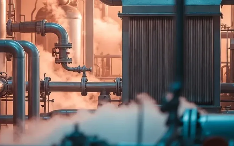
| Hot-water rinse and sanitize, 180–190°F | Steam-to-water shell-and-tube | High return temperature on once-through flow needs a steam approach a plate cannot give |
| Hot water at modest pressure, liquid heated | Gasketed plate pack, EPDM | Liquid-to-liquid at low pressure suits plates; EPDM is rated well past the duty |
| Return-to-makeup recovery | Gasketed plate pack, solution to solution | Returns 60–70% of the heat from a 150–160°F return against 60°F makeup |
| Worn bundle or hardened plate pack | New bundle or plate pack to the existing shell or frame | Keeps the shell, piping and frame; replaces only the part that wore out |
Three things to settle before you ask for a quote
Tank loop or once-through
- Tank loop: gallons, start temperature and the minutes allowed to reach target
- Once-through: circuit gpm and the temperature rise needed on a single pass
- A tank loop tolerates a slow steam valve; an inline heater needs one that follows flow in seconds
- Line flows run about 5 ft/s: 30 gpm in a 2-inch line, 120 gpm in 4-inch
Steam at the heater
- Pressure at the heater inlet, downstream of the control valve, not at the boiler
- 15 psig condenses at 250°F and still clears a 175°F caustic target
- Higher pressure means less surface but a hotter tube wall on the caustic side
- The trap and valve belong to the installation; the heater nozzle is sized for them
What fouls and what pulls
- Milkstone and protein build on the solution side, fastest above about 160°F
- U-bundle out for a soak or pressure wash; straight tube when the plant brushes
- A fouling allowance of 0.001–0.002 adds roughly 10–20% surface
- Leave bundle-lenght clearance at the head end when the heater is set, or the first pull becomes a repipe
Related
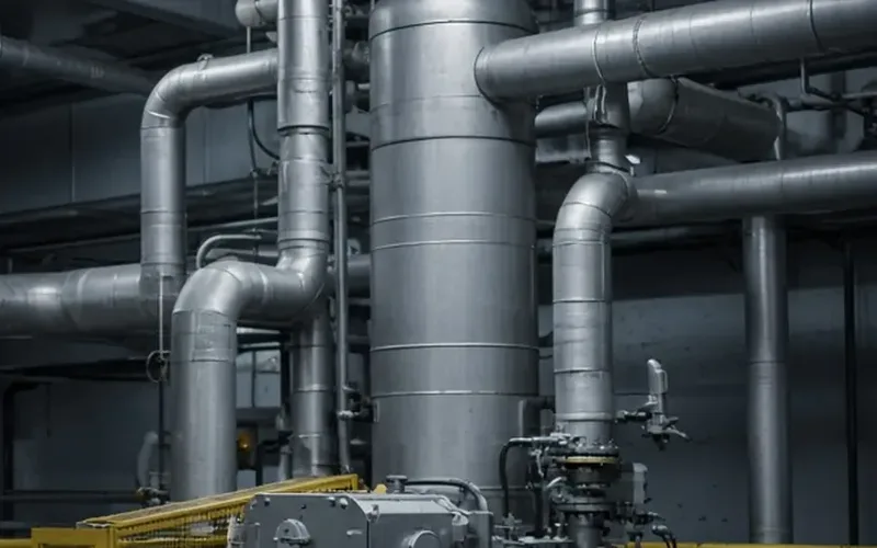
CIP Heaters
Steam-to-Caustic U-Tube
The construction behind most caustic heaters: steam condensing inside a U-bundle, caustic on the shell, and a bundle that slides out when the milkstone builds.
+ Learn More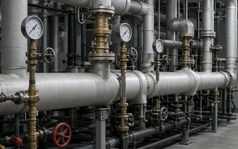
CIP Heaters
Steam-to-Water Shell & Tube
Steam inside the U-tubes, rinse water in the shell: how a once-through heater holds 185°F at 70 gpm on 15 psig steam, and what the control valve has to do.
+ Learn More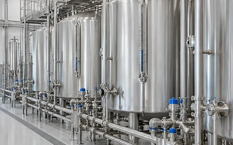
CIP Heaters
Return-to-Makeup
What the return gives up, what the makeup gains, the approach to expect, and the steam the finishing heater no longer burns, worked for a 100 gpm caustic circuit.
+ Learn More