
1-805-484-2992
Quotes - Engineering - SalesThe industrial build is a pressure vessel that happens to carry caustic
An industrial CIP heater is designed the way a utility exchanger in any plant is designed: an ASME Section VIII shell, 316L wherever the caustic or acid touches, carbon steel permitted on the steam head where only steam and condensate run, mill finish inside and out, and flanged or threaded nozzles that match the plant's piping. It is rated 150 psig at 250°F on the shell side and 150 psig at 400°F on the tube side, and it is the construction most CIP loops should be specified to.
What is in the build
The reason is what the heater carries. The solution side sees 1–2% sodium hydroxide at up to 175°F, dilute nitric or phosphoric acid at 120–150°F, and rinse water. All of it is a cleaning chemical that will itself be flushed out of the loop; none of it is product. A loop that the plant treats as a utility, with mill-finish pipe, flanged valves and a centrifugal pump off the shelf, gains nothing from a polished and drainable heater in the middle of it, and the plant pays for the polish on every square foot of shell.
What the industrial build does not give up is the thermal and mechanical design. The U-tube bundle is 3/4-inch or 1-inch 316L and pulls from the shell for cleaning; the solution-side head gasket is EPDM, or FKM where the acid step uses nitric hot or often; the fouling allowance of 0.001–0.002 on the shell side is carried in the surface. The difference between this unit and a sanitary one is finish, drainability and connection style, and nothing in the heat transfer.
Standard industrial specification
- ASME Section VIII shell, U-stamped, 150 psig at 250°F on the solution side
- Tube side 150 psig at 400°F, covering plant steam from 15 to 125 psig
- 316L shell, U-tube bundle and solution-side heads; carbon steel steam head optional
- Mill finish on all solution-contact surfaces, pickled and passivated after welding
- 150-pound raised-face flanges, or NPT on 2-inch and smaller nozzles
- EPDM head gasket standard, FKM on acid duty, retained in a confined groove
- Saddles or lugs for a horizontal mount, with a drain and vent on the shell
shell-side design pressureThe solution side is designed for 150 psig at 250°F even though a CIP loop rarely sees 60 psig, because the stamp, not the pump, sets the number.
When industrial is the right call
Choose the industrial build when the heater serves a loop the plant runs as a utility. The signs are in the loop itself, not in the product the plant makes.
- The CIP supply and return are mill-finish stainless pipe with flanged or threaded joints
- The CIP pump is a standard centrifugal with flanged ends, not a sanitary pump
- The tanks are utility stainless with manways, not polished vessels with sanitary fittings
- The plant's zoning map draws the CIP loop outside the product-contact boundary
- No inspector has asked to see a finish or a drain angle on the heater
Call and talk it through with an engineer: 1-805-484-2992
What the industrial build looks like in a plant
Picture a brewery cellar. The caustic tank is 1,500 gallons of utility stainless, the supply pump is a flanged centrifugal, and the loop runs 3-inch mill-finish pipe to the fermenters. The heater sits beside the tank on saddles, shell horizontal, steam head at one end and the U-bundle pulling out the other. The shell side carries caustic at 140–160°F; the tubes carry 15 psig steam from the cellar header. A thermometer on the shell outlet and a control valve on the steam line are the only instruments.
Everything the caustic touches is 316L: the shell, the tube bundle, the solution-side head and the nozzles. The steam head at the other end is carbon steel on this unit because only steam and condensate enter it; the plant could specify stainless there too, and a dairy with a washdown culture sometimes does, but it changes no part of the duty. The flanges are 150-pound raised face, matching the valves the plant already stocks.
The shell is stamped for 150 psig at 250°F. A CIP pump rarely delivers more than 60 psig and the caustic never passes 175°F, so the margin is wide; the rating exists because the shell is a pressure vessel and the code, not the duty, sets it's design point. On the steam side 150 psig at 400°F covers any plant steam from 15 to 125 psig, so a boiler upgrade later does not strand the heater.
Fouling on this unit is beer stone and protein film, and on a dairy it would be milkstone; either way it builds on the shell side where the solution runs. Twice a year the maintenance crew breaks the solution-side head, slides the bundle out onto a cradle and washes it in the yard; the mill finish takes a brush without complaint. The 10 feet of clearance in front of the shell was on the installation drawing, which is the only reason this is a two-hour job.
What the plant did not buy is a polished interior, a sloped shell and tri-clamp ends. If the brewery later decides that the CIP return is inside its sanitary boundary, this heater does not upgrade; it is replaced. That is a real limitation and the plant should make the zoning decision first. For a loop that stays utility, which is most of them, the industrial build does the same thermal work for less money and is easier to service.
Finish and fittings are the whole difference; the heat transfer is identical.
An industrial heater is specified by the loop it sits in, never by the product the plant makes.
Request a QuoteIndustrial build questions
Because the steam head sees nothing but steam and condensate, both of which carbon steel has handled in boilers for a century, and because a 316L head with a 316L tubesheet welded to it adds cost without touching the duty. Plants that hose down the area or want one alloy throughout specify stainless and we build it; the choice is theirs and changes nothing about the solution side.
Mill finish on 316L tube and plate is typically 40–60 Ra, smooth to the hand, and the soil that collects on a CIP heater is mineral scale and protein film that would form on a polished surface at the same rate, because they deposit by temperature, not by roughness. The caustic and acid that pass through the heater clean the mill surface on every cycle. The finish matters for inspection, not for cleaning.
Yes, on the solution side to 4 inches, and some utility plants ask for it to match pipe fittings they stock. It does not make the unit sanitary, because the finish and the drain layout are unchanged. We build it as a hybrid and call it that on the drawing so nobody later mistakes a clamp fitting for a certification.
The ASME inspector witnesses the hydrotest and signs the data report; the shell leaves with the stamp and the nameplate. Material test reports for the 316L follow the unit. There is no third-party sanitary review and no finish survey, which is where the sanitary and 3-A builds add their cost. For a utility loop the code paperwork is all the plant's own inspector will ask to see.
Related
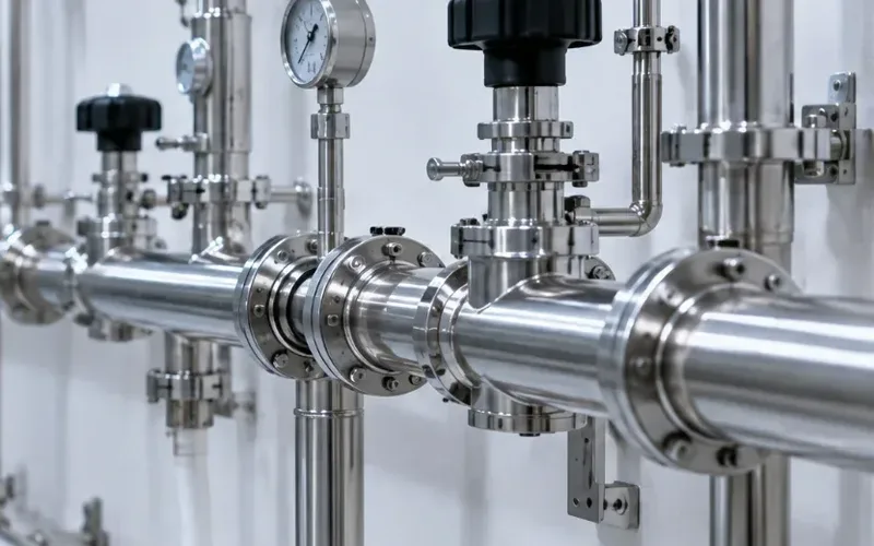
Sizing & Selection
Sanitary
Tri-clamp ends to 4 inches, a shell that drains without tilting, 32 Ra on the solution side and crevice-free gaskets. For loops inside the sanitary zone.
+ Learn More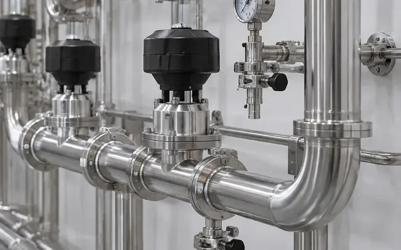
Sizing & Selection
3-A Sanitary
The 3-A symbol on a CIP heater means a third party reviewed the design against the sanitary standard. Who needs it on the heater and what it adds to the build.
+ Learn More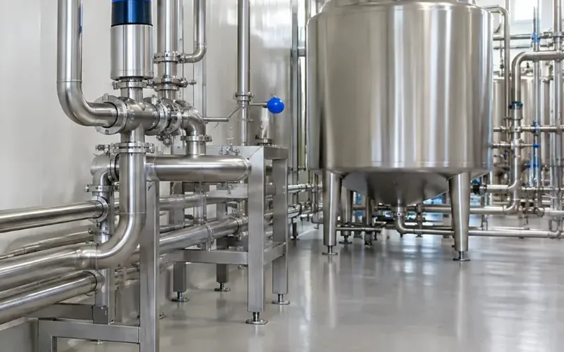
Sizing & Selection
Certifications & Design
Three build levels for the same duty, from mill-finish utility stainless to a 3-A marked drainable unit. Which one the loop needs, and what each adds to the cost.
+ Learn More