
1-805-484-2992
Quotes - Engineering - SalesHeating the supply flow in one pass
No tank behind it
An inline heater sits between the supply pump and the circuit and sees the entire flow the spray devices or pipeline take. Whatever enters it has to leave at wash temperature, every second, because there is no tank downstream to blend a cold slug away. Line circuits run about 5 ft/s, which puts 30 gpm through a 2-inch line, 70 gpm in 3-inch, 120 gpm in 4-inch and 200 gpm in 6-inch; a silo spray circuit may pull 100–300 gpm through the same heater.
The heat is simple to state: 500 Btu/h for every gpm raised one degree. A 100 gpm circuit lifted 60°F needs about 3 MBtu/h and condenses roughly 3,100 lb/h of 15 psig steam. What is not simple is that the flow changes. A circuit opens, a spray device is valved in, the return pump catches up, and the heater sees 70 gpm one minute and 120 the next while the target stays at 160°F.
So the inline heater is a U-tube steam heater with surface to spare and a steam control valve chosen for speed and turndown as carefully as the exchanger itself. Caustic on the shell side, steam in the tubes, bundle removable, as on any caustic duty.
See the U-Tube Removable Bundle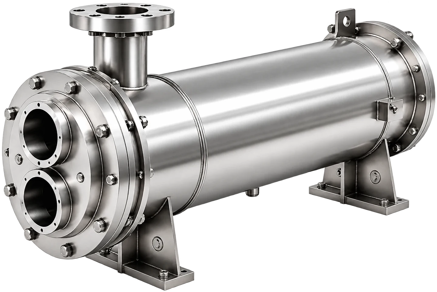
Inline caustic heater, typical conditions
The numbers that define a once-through caustic heater. Where the circuit flow varies, we size on the highest flow and check the valve at the lowest.
| Condition | Typical value |
| Circuit flow | 30 gpm (2-inch) to 200 gpm (6-inch); silo circuits 100–300 gpm |
| Inlet temperature | Makeup or return at 60–140°F, depending on recovery |
| Outlet temperature | 140–175°F, held within a few degrees at any flow |
| Duty | 500 Btu/h per gpm per °F; 100 gpm up 60°F is about 3 MBtu/h |
| Steam | 15–125 psig at the heater; 3 MBtu/h condenses about 3,100 lb/h at 15 psig |
| Steam valve | Modulating, sized for full flow with turndown to the smallest circuit |
| Construction | U-tube, steam in the tubes, caustic in a 316L shell, bundle removable |
| Rating | Shell 150 psig at 250°F; tubes 150 psig at 400°F |
What makes a once-through heater work
Size on the worst pass
The duty is set by the largest circuit at its coldest inlet. On a plant with recovery, the makeup may arrive at 130°F and the heater only adds 30°F; on the first wash of the day with the recovery exchanger cold, the same heater sees 60°F water and must add 100°F. If the heater is sized for the easy case, the first cycle runs cold and sanitation blames the chemistry. We size for the cold start and the biggest circuit, then confirm the steam valve can throttle down to the smallest circuit without hunting.
The steam valve has to follow flow
A tank loop forgives a slow valve; an inline heater does not. When flow steps from 70 to 120 gpm the steam demand steps with it, and a valve that takes a minute to open sends a minute of cool caustic down the line. The outlet temperature sensor should sit close to the heater, the valve should be a modulating type with a positioner, and the controller tuned for the fast loop. Feedforward from a flow signal, where the plant has one, takes most of the swing out.
- Sensor within a few feet of the heater outlet
- Modulating valve with turndown matching the smallest circuit
- Trap sized for the full condensing rate
- A high limit on outlet temperature to protect gaskets downstream
Surface margin and fouling
An inline caustic heater runs hotter than a tank heater because the whole temperature rise happens in one pass, so the tube wall at the outlet end sits closest to steam temperature. That is where milkstone forms first. We add the usual fouling allowance of 0.001–0.002 on the caustic side and prefer lower steam pressure with more surface where the plant can give it. The U-bundle pulls out at the steam-head end when the pressure drop or the outlet temperature starts to drift.
When the tank loop is the better answer
A plant with a large caustic tank, long idle periods and a modest circuit flow is better served heating the tank in a side loop and letting the circuit pump draw hot caustic. The heater can then be smaller and the valve slower. Tank recirculation works through that case; the two are not interchangeable, and an inquiry should say which one the plant runs.
Inline heater questions
Take the biggest circuit the heater will ever serve at its design velocity, about 5 ft/s in the line, and add the spray devices that can run at the same time. On a 4-inch supply that is around 120 gpm; a silo circuit with several spray balls at 25–100 gpm each can reach 300 gpm. Size the exchanger there and check the valve at the smallest circuit.
The coldest the heater will see, which is usually city or well makeup at about 60°F on a first wash, not the 130°F the recovery exchanger delivers once everything is warm. If the plant never runs without recovery, say so and we size for the warm case with a check on the cold one. The difference can be a factor of three in duty.
The steam valve is too big for the small flow and can not throttle low enough, so it opens and closes in steps and the outlet swings. A valve with real turndown, or two valves in parallel for large and small circuits, cures it. The exchanger is rarely the cause; a heater with spare surface only makes a sluggish valve more visible.
Yes, and on single-use CIP it often does. The exchanger is sized for the caustic step, which has the largest temperature rise, and the solution-side head gasket is specified for the acid step, meaning FKM rather than EPDM where nitric is used hot. Everything that touches solution is 316L, so the sequence of chemicals is a gasket decision, not a metallurgy one.
Plan on a few psi on the caustic side at design flow; we hold it low on a shell-side design so the supply pump sees little change when the heater is added. The steam side is set by the valve, not the heater. If the pump is already marginal on a long silo circuit, tell us and we will trade a little surface for a lower drop.
Related
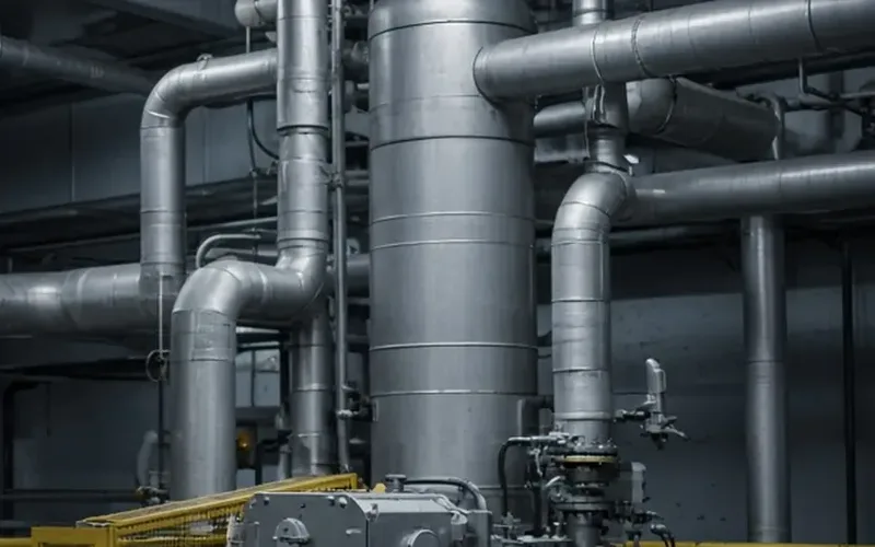
CIP Heaters
Steam-to-Caustic U-Tube
The construction behind most caustic heaters: steam condensing inside a U-bundle, caustic on the shell, and a bundle that slides out when the milkstone builds.
+ Learn More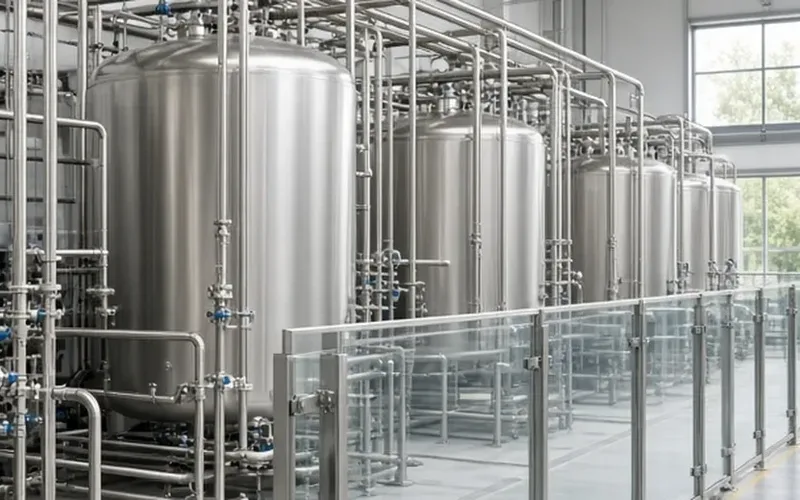
CIP Heaters
Tank Recirculation
A heater in the tank loop answers to gallons and minutes. How heat-up time sets the duty, what the loop pump has to move, and where the heater sits in the loop.
+ Learn More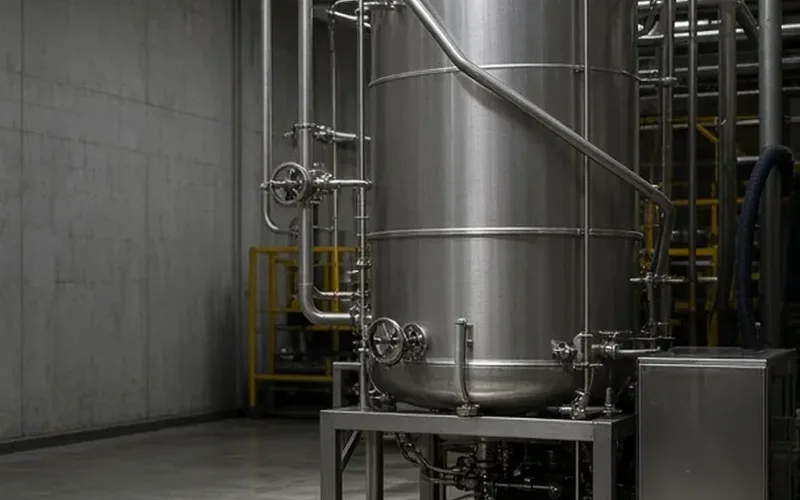
CIP Heaters
Caustic Heaters
Steam into a sodium hydroxide loop at 140–175°F: how the U-tube heater is built, and whether the tank loop or the supply line is the right place to put it.
+ Learn More