
1-805-484-2992
Quotes - Engineering - SalesWhy the U-bundle carries the caustic duty
Steam in the tubes, solution in the shell
Every caustic heater has one side that fouls and one that does not. Sodium hydroxide at 1–2% leaves milkstone, denatured protein and carbonate scale on whatever it touches while it is hot; condensing steam leaves nothing behind. So the caustic goes in the shell, where it washes over the outside of a tube bundle, and the steam goes inside the tubes. When the shell-side surface needs cleaning, the bundle comes out through the head end and the steam side is never opened at all.
The U-bend does a second job. Steam at 15 psig arrives at 250°F; at 125 psig it is 353°F. The tubes see that temperature within seconds of the valve opening while the shell is still at caustic temperature, and the difference in growth has to go somewhere. A U-tube bundle is fixed at one end only, so the tubes lengthen into the shell freely, with no floating head and no expansion joint to leak or crack after a few thousand cycles.
The result is a heater with a 316L shell, 316L U-tubes and a 316L solution-side head, with the steam head the only place carbon steel is acceptable. It is sized for the fouled condition, with a fouling allowance of 0.001–0.002 on the caustic side that adds about 10–20% surface over the clean calculation.
See the U-Tube Removable Bundle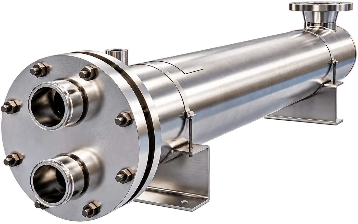
Standard build for a steam-to-caustic U-tube heater
Typical values for the construction we quote on caustic duty. Larger shells, higher ratings and code stamps are available when the plant asks for them.
| Condition | Typical value |
| Solution (shell side) | Sodium hydroxide 1–2%, 140–175°F |
| Steam (tube side) | 15–125 psig saturated, 250–353°F |
| Shell-side rating | 150 psig at 250°F |
| Tube-side rating | 150 psig at 400°F |
| Tubes | 3/4-inch or 1-inch 316L U-tubes |
| Wetted materials | 316L shell, bundle and solution head; carbon steel steam head on utility builds only |
| Head gasket | EPDM standard; FKM where the acid step passes through the same heater |
| Solution connections | Tri-clamp to 4 inches, flanged at 6 inches and above |
| Fouling allowance | 0.001–0.002 on the caustic side, none on the steam side |
Sizing and installing the U-tube caustic heater
Approach temperature and steam pressure
The driving force is the gap between saturated steam temperature and the caustic leaving the heater. At 15 psig that gap is about 75°F against a 175°F target and seldom less than 50°F once the valve has throttled; at 50 psig steam condenses at 298°F and the surface area drops accordingly. Low pressure means more tubes and a cooler tube wall, which slows milkstone; high pressure means a smaller shell and a hotter wall. We ask for the pressure at the heater inlet, downstream of the control valve, because a 100 psig header can arrive as 30 psig after a long run and an undersized valve.
Tube wall temperature and milkstone
Milkstone is calcium phosphate bound up in denatured protein, and it forms on the hottest surface in the loop. In a caustic heater that is the outside of the tubes, which sits a few degrees under steam temperature when the heater is running hard. Above about 160°F in hard water the deposit rate climbs, so a heater on 125 psig steam fouls visibly faster than the same duty on 15 psig. Where the plant has steam pressure to spare, we would rather use more surface at lower pressure than let the wall run hot.
Pulling the bundle
The bundle pulls out at the tubesheet end once the steam head is unbolted, so the installation needs a clear run at least the length of the bundle plus about two feet in front of that head. Many caustic heaters are set against a wall or under a tank platform with no clearance at all, and the first pull turns into a repiping job. Set the shell so the head end faces the aisle, support the shell on saddles rather than on the nozzles, and make the steam connections at the head with flanges or unions that come apart for the pull.
- Clear length: the bundle plus about 24 inches at the head end
- Shell on saddles, not hanging from the piping
- Head bolts and gasket reachable without a ladder
- Drain and vent on the shell so the caustic can be emptied before the pull
Full unit or bundle only
When an existing steam-to-caustic heater is tired, the shell is usually still sound; it is the bundle that has thinned at the baffles or lost tubes. A new U-tube bundle built to the shell dimensions and tubesheet drilling restores the heater in an outage of a day, and the piping never moves. Replacement bundles covers what we need from the old unit to build it.
Steam-side questions
Whatever reaches the heater inlet after the control valve, and we size to that number. Plant steam is usually 15–125 psig; 15 psig is enough for a 175°F caustic target because it still condenses at 250°F. Higher pressure buys a smaller shell at the cost of a hotter tube wall, which is the surface milkstone prefers to grow on.
Out of the bottom of the steam head through a trap sized for the condensing rate, then to the plant return. A 3 MBtu/h caustic heater condenses roughly 3,100 lb/h of 15 psig steam, and a trap that cannot pass it floods the lower tubes and strands part of the surface. The heater nozzle is sized for that flow; the trap and valve are part of the installation.
Not on treated plant steam. Condensing steam leaves no deposit, which is the whole reason it is inside the tubes. If the steam side is opened at all it is to inspect the tubesheet joints, and the U-bend end never has to be touched. Air binding, not fouling, is the steam-side problem to watch, so vent the head at start-up.
On a utility heater we will quote a carbon steel steam head, since steam and condensate never see the caustic. The tubes themselves stay 316L because the caustic is on their outside, and the tubesheet is 316L for the same reason. Where the plant treats the CIP loop as sanitary, the whole unit goes 316L and the question goes away.
As fast as the control loop asks. The U-bend absorbs the growth every time steam comes on, and a bundle anchored at one end only does not care how many cycles it sees. That is the difference from a fixed-tubesheet design, where each cold start works the tube-to-tubesheet joints. Six to ten wash cycles a day is normal duty for one of these.
Related
CIP Heaters
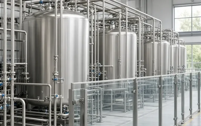
Tank Recirculation
A heater in the tank loop answers to gallons and minutes. How heat-up time sets the duty, what the loop pump has to move, and where the heater sits in the loop.
+ Learn More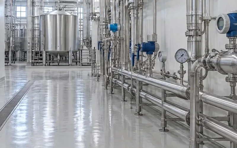
CIP Heaters
Inline Once-Through
No tank to average things out: an inline heater meets target temperature at circuit gpm on every pass. Line sizes, steam rates and the valve response it needs.
+ Learn More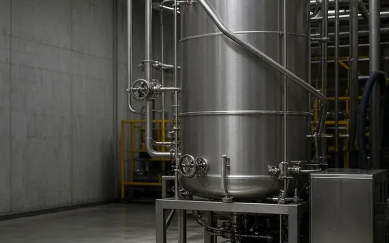
CIP Heaters
Caustic Heaters
Steam into a sodium hydroxide loop at 140–175°F: how the U-tube heater is built, and wether the tank loop or the supply line is the right place to put it.
+ Learn More